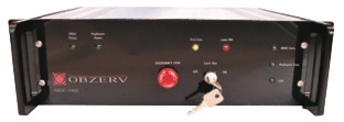
THE OBZERV MASTER CONTROL UNIT (MCU) is a 3U rack-mount, high-grade device that provides all the power and interconnection for a broad range of instruments in your surveillance camera system. On the back panel, connect a GPS, cameras, a radar, network cables; with fool proof mating and industry-standard connectors. The front panel provides on-site troubleshooting, via a series of information LEDs. You can also interrupt the system easily, at any time, with an oversized emergency stop button.
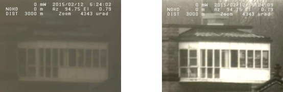
iSee™, Obzerv image enhancer and stabilizer, is used to process the analog video signal in order to provide image enhancement during daytime operation, video image stabilization and atmospheric effect reduction producing good quality images through fog, sandstorm, snow and rainy days.
No matter the distance of operation, the ARGC-2400 and ARGC-750 can further benefit of a built-in electronic stabilization algorithm with instantaneous correction between two images of 10% in horizontal or vertical movement, and 10° in rotation, no matter the frequency from 0 to 25 Hz.
This module is integrated in the Master Control Unit (MCU) and once enabled, process the various video feeds generated by Obzerv multi-sensor cameras. No need for an extra button or connection, everything is easily available to the camera operator.
IMAGE ENHANCEMENT USING COLOR SENSORS DURING DAYTIME |
|
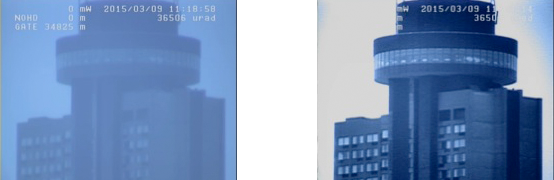
| 11:18 AM SNOWY CONDITIONS AND POOR VISIBILITY = 2 KM | |
| Without iSee™ | With iSee™ |
 |
|
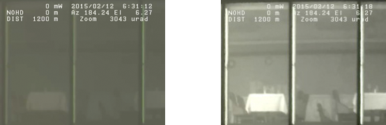
| Hotel at 1,2 km | |
| 6:31AM Rainy conditions and Average visibility = 10km | |
| Without iSee™ | With iSee™ |
 |
|
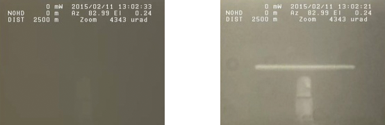
| Hotel restaurant at 1,2 km | |
| 1:02 PM Rainy conditions and POOR visibility = 3km | |
| Without iSee™ | With iSee™ |
 |
|
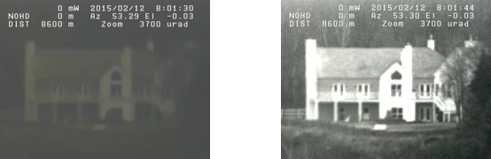
| Radar at 2,5 km | |
| 8:01 AM Good conditions and Good visibility = 40 km | |
| Without iSee™ | With iSee™ |
 |
|
| House at 8,6 km | |
| 6:24 AM Foggy Conditions and poor visibility = 2 km | |
| Without iSee™ | With iSee™ |
 |
|
| Hospital at 3 km | |
 |
|
| Bridge at 10 km | |
| Sand storm conditions and poor visibility | |
| Without iSee™ | With iSee™ |
 |
|
| Street at 150 m | |
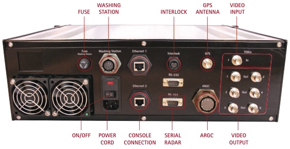
Fuse
10 A, 250 V MCU fuse.
Washing station connection
Control signals from the MCU to the water pump and from the water level indicator.
Console connection
The connection required between the console and the MCU for command and control is an Ethernet connection using a standard (direct or cross-over) CAT5 RJ45 cable.
Interlock connection
The Interlock is a safety mechanism that completely disables the laser emission when it is activated. The Laser Safety Officer (LSO) may use the Interlock connector to install several interlock mechanisms cascaded in series. The ARGC-2400 is shipped with a 50-ohm terminator installed on the Interlock connector.
Serial Radar Connection
Two serial links are available to connect the MCU to a radar station. The interface must be factory selected. The radar has to be connected to the RS-422 connector. You can slave the ARGC-2400 to the radar through the console software. The radar station will transmit the designated target coordinates to the Pan & Tilt through the MCU in order to pinpoint the ARGC-2400 at the target followed by the radar station.
GPS Antenna Connection
The antenna must be connected and well positioned for the GPS to get a valid satellite signal.
MCU connection (ARGC) to the Pan & Tilt/head unit
The ARGC-2400 is connected to its Pan & Tilt or the head unit with a multi-pin umbilical cable via the connector “ARGC”.
Video Input
Input any standard video signal from a surveillance camera;
Video Ouput
There are six video outputs named Out1 to Out6:
- The Out 1 is the ICCD output;
- The Out 2 is the color camera output;
- The Out 3 is the ICCD output or the color camera output as selected by the console (without overlay & electronic image stabilization)
- The out 4 and 5 are outputs of the selected sensors on the control software (electronic image stabilization and overlay can be enabled)
- The out 6 is the same as out 4 & 5 except that the overlay is always enabled.
-
ARCG power and positioner power will turn on when the system powers on.
- The MCU includes a laser key switch on its front panel that must be turned clockwise to enable the laser emission. When the interlock becomes active the amber Interlock LED turns on.
- The laser ON LED will blink rapidly when the laser is firing. This LED is active whenever the ARGC-2400 mode is active regardless of the power settings of the laser. This LED is not software-controlled.
- The ARGC COM LED blinks when a communication is established between the ARGC and the MCU.
- The positioner COM LED blinks when it is linked to the MCU.
- Link LED blinks when there is a communication between the MCU and the console.